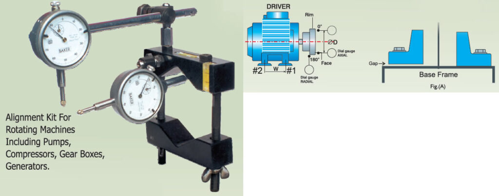
In any rotating machine coupled to a prime mover correct alignment would contribute significantly in enhancing life of couplings, bearings, seals etc. Rightalign alignment kit consists of an Aluminium vee Block that can be clamped on the Hub of coupling by wing nuts. The kit has two precision spirit levels in the vee block to get accurate indexing of 90°, 180°, 270°, 360°. Suitable extension pins, dial holder pins, clamps are provided to take care of different spacer lengths between couplings.
There is a facility of using two dials, one for measuring Radial misalignment and other for Axial. Both Radial/Axial readings can be taken simultaneously either by Rim/Face method in spacer type couplings or by using additional vee block in case of non spacer couplings like Lovejoy, Pinbush, Tyre couplings etc.
MODEL
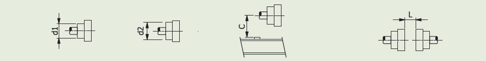
SELECTION CHART
MODEL
NO.
MINIMUM
HUB DIA d1
MAXIMUM
HUB DIA d2
GROUND
CLEARANCE 'C' MIN. (MM)
DISTANCE
BETWEEN COUPLINGS 'L' MAX. (M)
A0
30
60
90
200
A1
40
80
110
200
A2
55
120
150
200
A3
70
170
200
300
A4
120
260
300
300
A5
150
320
370
300
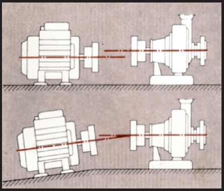
Alignment Of Shaft
Misaligned shafts will often cause problems with components in the machinery. Investigations made in USA have shown that misalignment can be traced as the cause of about 50 % of the breakdown in rotating machinery. Organized and implemented alignment of the shafts therefore is a very profitable form of preventive maintenance.
Two basic types of misalignment
The basic types of misalignments are parallel (offset) and angular. In practice these always occur in combination. The objective with shaft alignment is to adjust two units of rotating machinery so that the shaft of the units are in a straight line.
Misalignment and bearing life
The function and reliability of a machine de-pends to a large degree on how well its shafts are aligned. Misaligned shafts generate a moment which creates a reaction force in the bearings of the drive and driven units. A 20% load increase from misalignment reduces the calculated bearing life by almost 50%. Another serious effect is the wear on seals which will increase the risk of additional damage to the bearing by intrusion of contamination or leakage of the lubricant.
It is easy to understand that implementation of a well organized alignment program for critical machines will save cost and trouble. The service life of both bearings and seals will improve. Other spin-off effects are less vibration, noise and energy consumption.
Misaligned shafts may cause :
increased bearing load,
reduction of bearing life,
increased wear of seals,
increased vibrations,
increased noise, and
increased energy consumption
which will be avoided by proper shaft alignment.
STEPS TO BE TAKEN BEFORE STARTING ALIGNMENT
I . SOFT FOOT : It is the GAP between motor FEET AND BASE FRAME. (Ref. Fig.(A) THIS GAP SHOULD BE LESS THAN 0.05mm. To check soft foot, remove all existing Shime. Loosen bolts and check gap with FEELER GAUGE between ALL FOUR LEGS AND BASE FRAME. Either grind base frame to remove soft foot or ADD SHIMS between individual FOOT and BASE FRAME. THESE SHIMS SHOULD NEVER BE REMOVED, UNTIL MOTOR IS CHANGED.
2. ZERO Reference : If you start from 0° and come back to 0° after rotating by one circle the readings at 0° should match, otherwise check all tightening points and retighten. This is valid for both Dials.
3. 90-270 : This should be within 0.5mm if you check by a straight edge, if not correct it within 0.5mm
4. Axial Dial & Radial Dial should be as near as possible.
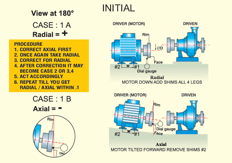
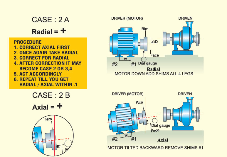
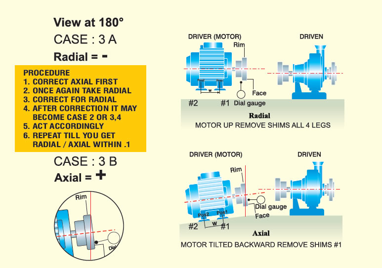
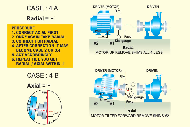
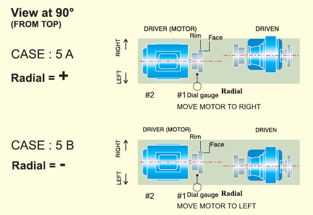
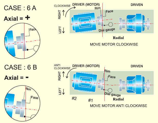
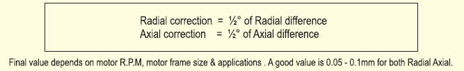
Radial correction is difference 0-180 / 2 for Axial Refer back page